Sunday, January 22, 2017

Seminar on TMT Bars


Saral Dutta,B.Tech(Hons)IIT
Executive Director(Retd) ISP&RMD,SAIL
Preamble
Thermo-Mechanical Treatment (TMT) is a metallurgical process that integrates work hardening and heat treatment into a single process resulting in bars having a hard outer surface with a softer core. This quenching process produces high strength bars from low carbon steel. TMT Bars are extra high strength reinforcing bars which eliminate any form of cold twisting, the technology of yesteryears. The need for cutting down the cost of production of high strength re-bars has initiated the involvement of a more economical and competitive Thermo Mechanical Treatment Process. TMT bars are produced as per IS1786:2008 for Fe 415 & 500 grade. The need for reduction in the steel used for concrete re-enforcement has prompted to switch to re-bars of higher yield strengths of 500 and 550 MPa.
TMT Bars are much stronger than conventional CTD Bars and provide up to 20% stronger concrete structure with same quantity of steel and shows up to 50% more elongation than conventional CTD Bars without compromising on strength which makes it safe in earthquake prone areas. Re-bars of yield strength up to 500 N/sq. mm. produced either by cold twisting or micro-alloying or a combination of both adds considerably to the cost of the re-enforcement bars. These cold twisted bars have inferior ductility, weld-ability and increased rate of corrosion. Production of re-bars by the addition of micro-alloys gives the desired results of high strengths but at a cost, which is prohibitive.
Thermo Mechanical Treatment process produces re-bars of high yield strength, superior ductility, weld-ability, bend-ability, better corrosion resistance and thermal resistance creating a revolution in re-enforcement engineering.
More strength with higher elongation makes a concrete structure sound and safe. TMT steel bars compliments “Reinforced Cement Concrete” (RCC) which has become an integral part of every structure, be it a multi-storeyed building, a tunnel, a flyover, or a TV tower. With TMT, RCC can be molded into any desired shape with which the steel rears will gain the ability to withstand any load made to act upon them. In composite RCC, the re-enforcing steel is the costliest constituent (30 to 40% per cu. m. of concrete). This cost can be substantially reduced by using higher grades of steel re-enforcing bars. The higher yield strength of re-bars lowers the steel requirement, which results in reduced cost of construction.
Steel billets are heated to approximately 1100°C in a reheating furnace and then progressively rolled to reduce to the final diameter of the reinforcing bar. After the ultimate rolling pass the hot steel bars are passed through a specially designed water-cooling system to receive a short & intensive cooling. A microprocessor controls the water flow to the quench box to manage the temperature difference across the cross-section of the bars. The correct temperature difference assures that all the metallurgical changes occur and bars attain the necessary mechanical properties

Thermo-Mechanical Treatment - Quenching Stages.
  • Surface quenching first stage begins when the hot rolled bar leaves the ultimate rolling stand, it is rapidly and intensively quenched by a special water spray system and the temperature is suddenly reduced drastically;. This drastic cooling measure converts the surface layer of the bar to a hardened structure called martensite while the hot core remains austenite.
  • Self Tempering second stage begins when the bar leaves the quenching box with a temperature gradient across its cross section, the temperature of the core being higher than that of the surface. This allows heat to flow from the core to the surface, resulting in tempering of the surface, producing a structure called tempered martensite which is both strong and tough. The core is still austenitic at this stage.
  • Atmospheric cooling final stage takes place on the cooling bed. The temperature difference between the core (which is still hot) and the cooled peripheral surface layer is equalized at around 6000 C. the austenitic core is transformed to a ductile ferrite-pearlite core.
  • Controlling parameters of Quenching
  • The equalizing temperature together with the finishing rolling temperature is the most important parameter to achieve the required mechanical properties.
  • Quenching time and Water flow rate


Effects of Quenching & Cooling
  • The resultant soft core forms about 65-75 % of the cross-sectional area (depending upon the desired minimum yield strength) and the rest is the hardened periphery.
  • There is a variation across the cross section, having a combination of strong, tough, tempered martensite in the surface layer of the bar, an intermediate layer of martensite and bainite, and a refined, tough and ductile ferrite and pearlite core.
  • TMT bars have undesired brittleness, superior tensile strength (high yield strength), ductility, toughness, hardness, stress free and resistance to corrosion,
  • Thus a high strength bar is obtained from inexpensive low carbon steel.
Microstructure Changes in TMT Process
Austenite
  • In iron-carbon alloys austenite is the solid solution formed when carbon is dissolved in face centered cubic gamma iron (γ-iron) having a maximum of about 2% C at 11300 C.
  • Coarse-grained austenite transforms to pearlite when it is cooled slowly below the Ar critical temperature.
  • However, when more rapidly cooled, this transformation is retarded.
  • Faster cooling rate to the temperature at which the transformation occurs result in the micro-constituent as mentioned.
Constituents
Temperature range
Pearlite
7050C to 5350C
Bainite
5350C to 2300C
Martensite
Below 2300C
.
Pearlite
  • It is very fine plate like or laminar in aggregate of ferrite and cementite.
  • It is the result of a eutectoid reaction which takes place at 7200 C when plain carbon steel of approximately 0.8% carbon is cooled very slowly from the temperature range where austenite is stable.
  • The white ferritic matrix makes up most of the eutectoid mixture together with the plates of cementite..
  • Average properties are tensile strength 120,000psi: elongation 20% in 2 in: hardness Rockwell C 20, Rockwell B-95-100, or B.H.N 250-300.

Ferrite
  • Ferrite is a solid solution - an interstitial solid solution of a small amount of carbon dissolved in α (B.C.C.) iron.
  • It is the softest structure in the iron-carbon diagram
  • The maximum solubility is 0.025% C at 7200 C and it dissolves only 0.008% C at room temperature.
  • Average properties are tensile strength 40.000psi elongation, 40 % in 2 in: hardness, less than Rockwell Co or less than Rockwell B 90.

Cementite or Iron Carbide
  • Interstitial compound of iron and carbon, Fe3C.
  • A very hard compound.
  • Tensile strength 5000 psi approximately.
  • Elongation in 2 inch is 0

Bainite
  • A decomposition of austenite bainite consists of an aggregate of ferrite and carbide.
  • Its appearance is featherlike, if formed on the upper part of the temperature range and acicular if formed on the lower part.
  • The hardness increases as the transformation temperature decreases.
  • This is due to a finer distribution of carbide in bainite formed at lower temperature.

Marten site - Transformation & Tempering
  • The martensitic reaction begins on quenching when the austenite reaches the martensite start temperature (Ms) and the parent austenite becomes unstable.
  • Austenite transformation to martensite continues till the temperature (M f) is reached, at which the martensitic transformation is completed. 
  • The martensite transformation occurs almost instantaneously - the proportion of austenite transformed to martensite depends only on the temperature to which it is quenched.
  • Martensite is not shown in the equilibrium phase diagram of the iron-carbon system because it is a metastable phase. It is the kinetic product of a rapid cooling of steel containing sufficient carbon.


  • Equilibrium phases are formed by slow cooling rates that allow sufficient time for diffusion, whereas martensite is formed by extremely high cooling rates.
  • Martensite is formed of austenite at such a high rate that carbon atoms do not have time to diffuse out of the crystal structure in large enough quantities to form cementite (Fe 3 C).
  • Face-centered cubic austenite transforms to a highly strained body-centered tetragonal form of martensite that is supersaturated with carbon.
  •  Martensite has a lower density than austenite, so that the martensitic transformation results in a relative change (increase) in volume.
  • Transformation induces a great deal of internal stress, often manifesting itself as cracks.
  • However, shear strain is more significant and produce large numbers of dislocations, which is a primary strengthening mechanism of steels.
  • More the number of dislocations, greater are the interlocking of dislocations causing obstruction to the movement of dislocations pin[ng the dislocations in place, which results in increase in strength.
  • The highest hardness of a pearlitic steel is 400 Brinell, whereas martensite can achieve 700 Brinell. 
  • Since quenching can be difficult to control, many steels are quenched to produce an overabundance of martensite.
  • The needle-like microstructure of martensite leads to brittle behavior of the material. Too much martensite leaves steel brittle, too little leaves it soft.

Retained Austenite
  • In many steels, the martensite transformation does not go to completion due to insufficient quenching (not quenched to the Mf temperature), resulting in varying amounts of retained austenite.
  • Mechanical properties are affected by a high percentage of retained austenite.
  • If the cooling rate is slower than the critical cooling rate, some amount of pearlite is formed, starting at the grain boundaries where it will grow into the grains until the Ms temperature is reached when the remaining austenite transforms into martensite.
  • Moreover, the percentage of retained austenite increases from insignificant for less than 0.6% C to 13% retained austenite at 0.95% C
  • The amount of retained austenite is a function of carbon and alloy contents and the quenching temperature
  • Austenite is the normal phase of steel at high temperatures, but not at room temperature. Because retained austenite exists outside of its normal temperature range, it is metastable and given the opportunity, transforms from austenite into martensite.
  • Higher amount of retained austenite after quenching and martensitic transformation at the surface increases the chance of distortion and danger of forming cracks in the specimen
  • However, a combination of austenite (soft and tough) and martensite (hard, strong and brittle) creates a composite material that has some of the benefits of each, while compensating for the shortcomings of both.

Tempering
  • It is necessary to modify the very strong but normally very brittle properties of Martensite by heat treatment (tempering) in the range 150-700°C.
  • Martensite is a highly supersaturated solid solution of carbon in iron, which, during tempering, rejects carbon in the form of finely divided carbide phases.
  • The end result of tempering is a fine dispersion of carbides in an α-iron matrix, which often bears little structural similarity to the original as-quenched martensite. 
  • The needed quantum of tempering is carried out until the right structure for the intended application is achieved.
  • Retained austenite does not remain stable during the tempering process
  • The as-quenched martensite possesses a complex structure. The first formed martensite, i.e. the martensite formed near Ms has the opportunity of tempering during the remainder of the quench.
  • This is auto-tempering, which is more likely to occur in steels with a high Ms.
  • Tempering takes place in distinct but overlapping stages:
Stage 1
  • Martensite formed in medium and high carbon steels (0.3-1.5% C) is not stable at room temperature because interstitial carbon atoms can diffuse in the tetragonal martensite lattice at this temperature.
  • These instability-increases between room temperature and 250°C, when iron carbide precipitates in the martensite.
Stage 2
  • Austenite retained during quenching is decomposed, usually in the temperature range 230-300°C.
  • Retained austenite decomposes to bainite, ferrite and cementite.
Stage 3
  • During this stage cementite first appears in the microstructure
  • This reaction commences as low as 100°C, and is fully developed at 300°C.
  • During tempering, there is replacement of low-temperature martensite by cementite and ferrite.
  • During the third stage of tempering it is, essentially, ferrite, not supersaturated with respect to carbon.
Stage 4
  • The cementite particles undergo a coarsening process and essentially lose their crystallographic morphology, becoming spheroidized.
  • The coarsening commences between 300 and 400°C, while spheroidization takes place increasingly up to 700°C.
  • The final result is an equiaxed array of ferrite grains with coarse spheroidized particles of Fe3C partly, but not exclusively, in the grain boundaries.

Role of Carbon Content
  • The hardness of the as-quenched martensite is largely influenced by the carbon content.
  • Carbon has a profound effect on the behavior of steels during tempering.
  • The Ms temperature is reduced as the carbon content increases, and thus the probability of the occurrence of auto-tempering is less.

Microstructure of TMT Bars
Three distinct rings appear when the cut ends of TMT bars are etched in Nital 
  • Tempered surface layer / outer ring of martensite.
  • Semi-tempered middle ring of martensite and bainite.
  • Circular core of bainite, ferrite and pearlite.

BIS - Mechanical Properties
Fe 500 Fe 500-D
Yield Stress- YS (N/mm2) 500 500
Ultimate Tensile Stress- UTS (N/mm2) 545 565
UTS/YS Ratio 1.08 1.08


Grades
  • The grades of TMT bars depend on the various chemical compositions the steel,
which determine the various characteristics such as , malleability, hardness, etc.
  • Carbon is restricted to below 0.20% for imparting better ductility and bend-ability and to ensure better weld-ability.
  • The carbon equivalent of the steel is controlled by the addition of manganese (from 0.50% to 1.2% depending on the grade of the TMT bar being produced.
  • In corrosion resistant TMT bars, corrosion resisting elements are suitably added in the steel.
  • Sulphur and phosphorus maintained below 0.05 %

BIS - Chemical Analysis
Fe 500 Fe 500-D
% Carbon 0.300 0.250
% Carbon Equivalent (CE) 0.420 0.420
% Sulphur (S) 0.055 0.040
% Phosphorus (P) 0.055 0.040
% Sulphur & Phosphorus (S&P) 0.105 0.075
% Nitrogen (PPM) 120 120 1

The consistency in strength across the rebar is maintained by reducing the impurities like sulphur and phosphorous to a level below 0.075%. '500' refers to the strength of the rebar in MPa and 'D' refers to ductility of the rebar.


CTD & TMT Bars Compared

PROPERTIES
CTD/Plain Bars
TMT Bars
Strength

Low strength.

Higher strength even at elevated temperature with high ductility.
Do not need more work hardening. and so torsional stress cannot form surface defects
Formability
Lower formability.
Excellent formability due to uniform elongation
Weldability
Welding avoided due to weak welded joints
No loss strength on welding.
Formability
Bend 3D to 5D Rebend 5D to 8D (D=Diameter of bar).
Very High Bendability
Bend ID and Rebend 4D.
Fire Hazards
Loss of strength due to temperature rise.
No loss of strength up to 5000C.
Ductility & Fatigue Strength
High.
Very high. Most suited for earth quake resistant structures and equipment foundations.
Corrosion Resistant
Scales fall down during cold twisting.
Better corrosion resistant. Absence of cold stress means longer life of concrete structure.
Workability

(i) Pre-welded meshes is used to eliminate manual binding at site; saving construction time.
(ii) Easy working at site due to excellent features of ductility and bendability reduces fabrication time.
Transportation
Cost
Higher manufacturing cost
Comparatively lower manufacturing cost.
.
Overall Economy

(i) Availability of higher grade like 500N/sq.mm and 550N/sq.mm.
(ii) Lesser requirement of bar length in welding as compared to mechanical anchorages and results in overall saving.
(iii) Material saving, Saving in labour cost of bending binding etc.

TMT Rolling Process.
Applications
  • General purpose concrete re-enforcement structures
  • Bridges
  • Flyovers
  • Dams
  • High rise buildings
  • Industrial structures
  • Concrete roads
  • Underground structures

Why choose TMT BARS?
  • Ductility & Strength
Higher yield strengths combined with better elongation values and toughness as compared to conventional CTD bars resulting in saving of steel and cost of transportation.
The process used ensures combination of tempered martensite on the surface with fine grain ferrite-pearilite and austenite in the core providing for higher tensile strength, toughness ductility and imparts quality of fatigue resistance on dynamic loading on account of the high strength of the surface layer.
Better Safety of structures because of higher Strength combined with higher Ductility.
Strength of the TMT product depends on :
  • Carbon equivalent.
  • Temp after finishing pass.
  • Water pressure.
  • Diameter of the TMT Bar being rolled.
  • Cooling tube condition i.e. if tube is worn out, then pressure required is more.

  • Bendability
Easy working at site owing to better Ductility and Bendability.
Controlled quenching results in adherence to martensite ring formation with fine grain ferrite-pearilite and austenite soft core of TMT bars causing uniform elongation and excellent bendability. These bars can be subjected to Bend ID and Rebend 4D easily. This results in lot of advantages formability during construction work. Due to very high elongation values and consistent properties throughout the length of bar, TMT rebars have excellent workability and bendability.

  • Higher Weldability
TMT bars have excellent weldable properties due to carbon being restricted to below 0.20% together with low carbon equivalent
They can be butt-welded or lap-welded using ordinary coated electrodes of matching strength. In manual arc welding no-pre warming or post-welding treatment is necessary.
TMT Bars are produced from IS 2830 Billets. Hence, due its lower carbon range it can be used in making of pre-welded meshes. The same is done without reduction in strength of weld joints. Pre-welded meshes eliminate manual binding at site. Reduces construction and fabrication time.
higher manganese results in, exceptional ductility and improved scope for welding. Low sulphur & low phosphorous nullifies the problems of “Hot Shortness” & “Cold Shortness”.

  • Thermal Stability
Resists fire. It can be used successfully even till 6000 C without any significant sacrifice in strength. Unlike Tor steel/ CTD Reinforcement bars, TMT bars have high thermal stability. They are the preferred choice when elevated temperatures of 400-6000 C may be encountered (Chimneys, fires).

  • Superior Corrosion Resistance
The TMT process gives the bar superior strength and anticorrosive properties. Bars produced by Thermo Mechanical treatment show virtually no rusting even after a long time, as there is absence of any tensional residual stress.Controlled water-cooling prevents the formation of coarse carbides, which has been cited as the main cause for the corrosive nature of common bar. The absence of surface stresses caused by the cold twisting process] contributes to the anticorrosive properties.

  • Malleability:
TMT bars are most preferred because of their flexible nature

  • Monolithic Bond Concrete Strength
  • Despite steel and concrete are two different materials, it is desired that these should form as a single unit in a reinforced structure.
  • Concrete grips the TMT steel bars to form the strongest bond because of the unique pattern, greater depth, closer and uniform rib spacing. External ribs running across the entire length of the TMT bar adds to the superior bonding strength between the bar and the concrete.
  • TMT bars make structures strong, safe and to last for generations. Fulfils bond requirements as per IS: 456/78 and IS: 1786/85.
  • Two main loading conditions that concrete under goes are compression and tension.
  • Steel is weak under compression but is strong at withstanding tensile stress (bending forces).
  • Concrete is superior at bearing compressive stress (squeezing forces) but is very weak in Tension (pulling) and can crack under tensile stress.
  • Moreover, concrete's weakest rating is in its shear strength. To increase concretes shear strength, TMT steel bars are used because of its high shear strength characteristic.
  • Concrete reinforced, i.e., strengthened with steel combine these qualities to create a material that is stronger than either material alone.
  • The strength of one offsets the weakness of the other.
  • Reinforced concrete is made by forming the concrete inside a metal or timber framework or by casting the concrete around ridged steel rebars called (reinforcing bars).
  • Stressed or pre-stressed concrete involves molding wet concrete around pre-tensioned steel wires. The wires compress the concrete as it sets, making it much harder.
  • The coefficient of thermal expansion of concrete is similar to that of steel, eliminating large internal stresses due to differences in thermal expansion or contraction.
  • When the cement paste within the concrete hardens, this conforms to the surface details of the steel, permitting any stress to be transmitted efficiently between the different materials. Usually steel bars are roughened or corrugated to further improve the bond or cohesion between the concrete and steel.
  • The reinforcement steel bar has to undergo the same strain or deformation as the surrounding concrete in order to prevent discontinuity, slip or separation of the two materials under load.
  • Maintaining composite action requires transfer of load between the concrete and steel. The direct stress is transferred from the concrete to the bar interface so as to change the tensile stress in the reinforcing bar along its length, this load transfer is achieved by means of bond (anchorage) and is idealized as a continuous stress field that develops in the vicinity of the steel-concrete interface.

  • Earthquake/ Seismic Resistance
  • The soft ferrite-pearlite core enables the bar to bear dynamic and seismic loading.
  • Excellent cold forming higher ductility, bend-ability and higher Fatigue strength makes it suitable for structures and foundations subject to dynamic and seismic loading
  • In earthquake prone zones Indian Code does not permit use of steel bars with less than 14.5% elongation.
  • TMT bars guarantee higher UTS to Yield Strength ratio and elongation percentage well above 15% - 18% even for FE 500 grade.
  • High UTS/YS ratio and more percentage elongation signify that the steel is capable to strain harder, in the event of an earthquake, i.e., have high fatigue resistance to seismic loads
  • Thermo mechanically treated rebars impart strength and ductility to RCC structure to withstand various kinds of loads impacting a building.
  • Superior resistance to sustain stress without failure prevents buildings from collapsing


  • Steel Economy
Quality Compared TMT Fe-415  TMT Fe- 500 TMT Fe- 550

IS: 2062 Gr.              40%              44%              48%
Plain Bar 
IS: 1786 Fe: 415        12%           14%               19%
HSD Steel Bar 

  • Cost-effective:
Section       Grade of Steel         Cost Saving w.r.t. (in %)
                                                                    Plain Bars     CTD Bars
Doubly Re-inforced CTD 415        28 - 33
Beam                   TMT Fe-500      34 - 37           12 - 14
                                  TMT Fe-550      38 - 42

Axially Loaded       CTD 415         32.0                
Columns                TMT Fe-415    39.0                 10.4

Uni-axial Bending CTD 415           28.0                 
with Compression TMT Fe-415     34.0                  8.0

Conclusion
  • Higher tensile strength and ductility (superior elongation) values enable economy in design, construction of high risers with improved earthquake resistance (better seismic resilience).
  • TMT bars have the added advantage of superior weldability, corrosion resistance) and durability.
  • Desired properties are attained with lesser amounts of alloying elements thereby reducing the production cost.
  • Achieves great savings in usage of steel to the extent of about 17% as compared to ordinary steel bars and thus reducing transportation costs.

Saturday, January 21, 2017

Setting a course for this blog.

One observation I made during my years managing steel plant production was that engineers who had to make technical decisions were frequently constrained  by the lack of the right reference information at the right time.Too many organizations have no training scheme for young engineers worth the name, fewer have access to a good library.

I hope to make this blog a repository of practical articles ( and links to practical articles) with the view of adding my little bit to  "skill India."Let us see how things develop.

AN INTRODUCTION TO THE COLD ROLLING OF STEEL


                            Gautam Ganguli, B.Tech(Hons).IIT Kharagpur

                            Ex-President,BRG Group of Industries


1.0 Introduction   

Rolling is the  process by which the shape of a piece of metal is changed by passing it between a pair of rotating rolls. When the process takes place at high temperatures(i.e. above the recrystallization temperature), it is called hot rolling. At temperatures below the recrystallization temperature ( typically at room temperature), the process is called cold rolling.

Hot rolling has two types of products: sections and flat products. Cold rolling is restricted to flat products only.

The rationale for hot rolling is the fact that metals are have a far lower yield strength at elevated temperatures; the deformation processes  therefore require far less energy, and in many cases are only practicable at  these temperatures.

 Cold rolling is exclusively used to produce thin gauges of flat products of superior surface  quality . The surface texture being free from the influence of mill scale, and being burnished by deformation by  polished  steel rolls is far superior to that producible by hot rolling.Very thin gauges(which can go down to  down to 100 microns for steel and 10 microns for aluminium) are in fact only producible by cold rolling on on precisely engineered  cold  rolling mill equipment, and not by hot rolling.

As far as steel is concerned, the bulk of the production of steel for cold rolling is in the low and very low carbon steel ( carbon content of 0.05% C or less)  segment. The steels are divided into categories such as commercial , deep drawing(DD),  extra-deep drawing(EDD), interstitial free(IF) and so on. Guaranteed properties of formability, drawability, paintability, surface texture , flatness ,uniformity of gauge etc. are to be provided to the customer.

Since the ductility of cold rolled strip is  impaired by the production process, annealing ( under a controlled furnace atmosphere to prevent scaling and thus preserve the surface) is very frequently carried out to improve the physical properties for downstream use.


2.0 Rolling loads.

Metal under deformation generates forces on the rolls; the housing retaining the rolls resist them.

To understand these forces we use the concept of the neutral section, and the friction hill.

Let \(v_0\) be the velocity of the strip entering the rolls, and \(v_1\) be the velocity exiting it.Obviously \(v_1\)>\(v_0\).

Experimentally it has been established that the horizontal component of the roll velocity \(v_n\)is such that \(v_1\)>\(v_n\)>\(v_0\). The section of the strip where the strip velocity is equal to  the horizontal component of the roll velocity is called the neutral section.

From the strip entry to the neutral section the strip is moving slower than the roll surface; hence frictional forces are dragging the strip towards the neutral section.This is called the region of 'backward slip". From the neutral section to the strip exit  the strip is moving faster than the roll surface;the frictional forces are also dragging the strip  towards the neutral section.This is called the region of "forward slip."

Experimentally, the curve of the specific rolling load, which is analogous to yield stress -except that the resistance to deformation is quite different from that which occurs in a tensile test, hence the values are different - in Pa  vs. the distance from the strip exit is of the form shown in figure 1. The shape of the curve, which is the result of friction, is called the friction hill.

The rolling load will be in the form of
Load=Specific load X contact area X tension factor, which translates into
\(P=P_m\sqrt{R\Delta H} n{'''}\)
where P=Rolling Load in N/m width of strip.
   \(P_m\)=Specific rolling load, in Pa
   \(R\Delta H\)=Area along the arc of contact/ m width of strip, sq m
   \(n{'''} \)  = tension factor
For practical use this is inadequate; the expression for contact area has to consider roll flattening which is important for thin strip, and the determination of Pm, which is influenced by the coefficient of friction, strip yield strengths and work hardening, and the strip front and back tension is not simple. Qualitatively we understand that rolling load goes down when:

a) the coefficient of friction is reduced.
b)  the work roll diameter is reduced.
c)the front and back tensions are increased.
d) the yield strengths of the metal, both before as well as after the reduction, are reduced.


The accurate prediction of rolling loads,torques,power etc. Is a complex task, and has been studied over decades by several authorities,each with different models,formulae and sets of experimental results, and a deviation of around 15% among them.Engineering companies have each selected their particular model, and are constantly validating and tweaking their formulae based on statistical mill data to present results that satisfy the users.


                            Figure 1


I am presenting below some formulae to calculate the specific load based on those developed by A.S.Tselikov, and published in his book Stress and Strain in Metal Rolling( Mir Publishers) :

1.\(\delta=\mu.\frac{2l}{\Delta H}\)
where
\(\mu\)= coefficient of friction
l=horizontal projection of the length of the arc of contact.
\(\Delta H=h_0-h\)
\(h_0\)= strip thickness at entry
\(h\)= strip thickness at exit.

2. \(n^{'''}=1-(\tau_0+\tau_1)/2P_m\)
\(\tau_0\)=entry strip tension/ entry strip cross-sectional area
\(\tau_1\)=exit strip tension/ exit strip cross-sectional area
\(P_m\)=Specific rolling load in Pa.

3.\(h_n/h_1=( 1+\sqrt{1+(\delta^2-1)(h_0/h_1)^{\delta}}/(\delta+1))^{1/\delta}\)
\(h_n\)= strip thickness at neutral point.

4.\(k=1.15(\sigma_0+\sigma_1)/2\)
\(\sigma_0\)=yield strength of strip at entry.
\(\sigma_1\)=yield strength of strip at exit
N.B. The two yield strengths are different owing to the different amounts of work hardening.

5.\( P_m=2k(2h_1/(\Delta h (\delta-1))(h_n/h_1)((h_0/h_1)^{\delta}-1). n^{'''} \)

There is an additional complexity regarding the calculation of the contact area; that has to do with roll flattening.

                                Figure 2

The rolling of thin gauges is characterized by relatively low contact areas and very high specific loads.  Under these conditions, work rolls flatten significantly in addition to deflecting parabolically( see para 3.0, crown and shape) .In  figure 2, the contact area follows the arc AO rather than BO, increasing the contact area.

Along the length of the roll, therefore, there is the working length which is in contact with the strip and  experiences roll flattening, and the non-working length not in contact with the strip where the roll section is circular once more.Between the two, at each end, there is a zone of transition which starts towards the ends of the working length and continues beyond.The roll bite changes from its parabolic shape; this phenomenon is called the edge drop, and is troublesome particularly in the rolling of thin gauge strip.

The following formula is applicable:\(l=\sqrt{R\Delta h+x^2}+x\)

where l is the contact area /mm width of strip, sq mm.

and
\(x=P_m/9500\) mm for steel work rolls.

\(x=P_m/28700\) mm for tungsten carbide work rolls.

This is the formula to calculate the power consumed by the mill motor :

\(N={P_m}^{'}\nu_1 Q_1\ln \lambda\)

Where \({P_m}^{'}=P_m+(\tau_0+\tau_1)/2\)

\(\nu_1\)=exit velocity of strip

\(Q_1\)= cross sectional area of strip as it emerges from the rolls

\(\lambda\)= the reduction ratio

Rolling torque  is given by

 \(M_{rol}=({P_m}^{'}\ln \lambda+\tau_0-\tau_1)Q_1D/2(1+s)\)

where
D= work roll diameter
s= forward slip.


To reiterate: a number of other researchers have also given their formulae for the calculation of these parameters; some of which are extensively used.

3.0 Crown and shape.

The art of cold rolling lies in keeping the rolled strip flat during and after  production.


                                 Figure 3

Figure 3 shows the direction of forces on the work rolls during rolling.There is an upward force on the top roll( and an equal and opposite downward force on the bottom one) exerted by the metal being deformed. Counterbalancing and opposite forces are exerted by the rolling mill housings through the journals at the roll necks.Each roll can therefore be considered to be a simply supported beam which deflects along the arc of a parabola; the roll gap is no longer rectangular but parabolic in shape.


                                  Figure 4

In case the strip shape follows the contours of the roll shape the rolling process is stable.Otherwise, there is a horizontal component of the forces exerted by the work rolls on the strip which tends to make the strip crumple laterally, and rolling is disrupted.

These considerations have strongly influenced both the  design and  operational practice in cold rolling mills.

3.1 Influence on cold rolling mill design.
One way to  reduce the parabolic deflection of the work rolls is to reduce the rolling load, which means that the work rolls should be as small in diameter as possible.This led to the concept of 4-hi mills, where the work rolls are supported by backup rolls of much larger diameter which lends rigidity without increasing the rolling load.


                                 Figure 5

In frequent use are single stand reversing mills with tension reels at each end like the mill shown in figure 5, and tandem mills in which the strip passes from start to finish only once,like the mills shown in figure 6:

                                                                           Figure 6

A related development is of the Sendzimir ( or Z) Mills, where not only are work roll diameters considerably reduced, but the backup consists of tiers of support rolls, ultimately ending up in large roller bearings assembled on shafts and supported at intermediate points along the depth of an integrated housing.

                                   Figure 7

The mechanical complexity of the Z Mills , and the difficulty of producing absolutely flat products have stood in the way of the general popularity of these mills.However for specialty products like austenitic stainless steels (which work-harden rapidly), these are the mills of choice.


                                 Figure 8

The development of the 6-hi Mill has been to counter edge drop and is relatively recent.A pair of  intermediate rolls between the work and backup rolls, each tapered at one end, laterally movable inwards or outwards through hydraulic cylinders , allows the possibility of producing very flat coils of very thin gauges.They have virtually taken over as the mills of choice for the cold rolling of steel.


                                   Figure 9

Figure 8 describes the design principle of  6-hi mills, and figure 9 shows the picture of an installed single stand reversing 6-hi mill.

3.2 Influence on operating practice.
We introduce the term crown to mean the difference between roll diameter at the center and the roll diameter at the roll ends.This is usually a fraction of a millimeter.
3.2.1 External crown. By grinding the work rolls to have a slight positive parabolic crown to offset the negative crown caused by deflection.All roll grinders are equipped with mechanisms to generate a positive( usually) and negative(in some special cases) crown.
3.2.2 Thermal crown. Heat of rolling is generated at the work roll center, and the heat is mostly dissipated through the journals.This is despite a flood of roll coolant which constantly circulates during rolling.There is a temperature difference between the roll center and the roll ends which translates to a positive crown.
3.2.2  Roll wear. The work roll wears during rolling; the center wears more than the ends.This translates to a gradually increasing negative crown. This leads to a necessity of roll changes after a limited amount of production.
3.2.3  Drafting practice.By altering the percentage reduction in a given pass, the rolling load can be increased( leading to an increased negative crown) or reduced( the negative crown is reduced) .
3.2.4 Differential cooling.For reasons that will be discussed later, cold rolling is almost always carried out with roll coolants flooding the rolls. By dividing the cooling sprays into individually controllable sections, and programming the flows to the sprays to be computer controlled, it is possible to control the shape of the roll bite quite closely.By taking the input signals from special shape measuring rolls installed at the exit of the work rolls an automatic shape controlling device is created .This is a fine control, installed in high-end mills,as against the ones described earlier which are coarse controls, and are used in all mills.
3.2.5 Modern mills are equipped with a "work roll bending" feature.Small bore hydraulic cylinders built into the work roll chocks generate an additional controlled force tending to bend the work rolls at the roll necks.
Although  the bending force is usually around one-tenth of the rolling load, this  has a significant effect on the edge drop, and is an important operating control to maintain strip shape.


4.0 Mill Drives.
Mills have been designed to operate, and are operating at maximum speeds of 1600 meters per minute or higher(Mach 5). The tension reels at either end, and the mill motor or motors are all variable speed motors ( either DC or AC), with an integrated DC( or AC) Drive system  that couples accelerations, velocities and decelerations to work seamlessly together.

The concept of base mill speed is important.DC motors are designed with the concept of a maximum base speed, where speeds from zero to base speeds are increased by increasing the armature current, and from base to maximum speeds by weakening the field current. The speed-power and speed-torque characteristics are different in the two ranges. Variable speed AC motors have similar characteristics. These are conceptually shown in Figure 10 below:


                                  Figure 10

The ratio between maximum motor speed and base motor speed depends on motor design.

As can be surmised, this ratio is an important consideration for tension reel motors,  which must operate with constant motor power  at the desired rolling speed  to ensure constant tension.The diameter of the expanded tension reel drum is frequently  around 500 mm; while the maximum coil dia demanded is 2000 mm.This calls for a ratio of 4:1.

In practice, motors with ratios above 3.5:1 are scarce.This places a constraint on the maximum coil diameter; alternatively, some wraps must be  rolled with a lower tension than the rest of the coil.The practice required must be carefully selected at the mill design stage, as it cannot be reset during operations.

5.0 Strip thickness measurement and Automatic Gauge Control.

X-ray Gauges or Isotope Gauges are used to measure the thickness of the strip .The principle used is that the strip thickness is proportional to the fraction of the incident radiation ( X-rays for X-ray gauges, and gamma rays for isotope gauges) absorbed ; the remaining radiation being measured by the detector.

 X-ray gauges were the first to be used.Mechanical unreliability and the fact that the radio-active  sources generate gamma rays spontaneously caused isotope gauges to be preferred for a long time.Americium 241 is the isotope commonly  used for steel.

Recent improvements in technology, and the safety and  regulatory issues with isotope gauges have brought X-ray gauges back into popular use.

Signals from the  thickness  gauges are linked to hydraulic cylinders in the mill which allow the mill draft to be altered continuously on the fly based on the gauge signals.
Three modes of feedback are used: feedback, feed-forward andf constant load.


6.0 Preparation of hot rolled coils for cold rolling.
The surface of the coil must be completely free of scale. In addition, for metals that have a large resistance to deformation, the hot rolled coils must be annealed as well.
For mild steel, hot rolled coils are pickled in a Pickling Line, with hydrochloric acid being the most common pickling medium in use today. Stainless steels and high silicon electrical steels  are processed in Annealing and Pickling Lines where the steel is annealed , and then pickled in a single Processing Line.


                                  Figure 11

Picture of a medium production push-pull Pickling Line for steel.


7.0 Measurement and specification of surface roughness


                                 Figure 12

Surface roughness is measured in microns and is given by the formula: \(R_a=1/L\times\int_0^L h_i dx \)
where L is the sampling length(usually 0.8 mm)
The reference level is at the maximum peak
The datum level is at the deepest valley
The mean is chosen so that the arithmetic sum of areas of the peaks and valleys =0
\(h_i\) is the positive value of the distance from the mean to the point of measurement.
An instrument is used to read out the  \(R_a\) value from a spot on the selected surface in microns ,\(\mu\).


8.0 Roll coolants

Given the considerable amount of slip tht takes place during rolling and the demands of a high and consistent surface quality, the maintenance of a consistent and low coefficient of friction between the strip and the work rolls is a factor of considerable importance. The removal of the heat and the impurities generated by cold working and friction is another important consideration.The impurities are usually iron( metallic particles as well as oxides), and oxidation products of the lubricant used.This is achieved through the application of a roll coolant (usually an emulsion) specially engineered for the purpose. In addition to stabilizing the cold rolling process, roll coolants produce uniform surfaces of low surface roughness and high brightness.
Oil-in-water emulsions are used.Good emulsions plate out much of the oil to form a film of neat oil on the roll and strip surfaces at the roll bite.Low emulsion stability, large emulsion droplet size and a high SAP value are desirable properties of a good emulsion.
Note:
The saponification number or SAP value is defined as the number of milligrams of potassium hydroxide required to neutralize the fatty acids resulting from the complete hydrolysis of 1 gram of the sample.
The control over the lubricant required( maintenance of flow,temperature, oil content in the emulsion, scum removal, sludge removal,iron build-up) requires the installation of a Roll Coolant System.

Variation of the coefficient of friction with mill speed


                                 Figure 13

The coefficient of friction for a particular roll coolant is not constant, but varies with mill speed. The coefficient is highest at very low speeds, gradually falls with an increase in  mill speed till around 7.5 mps and  rises slowly at higher speeds.

9.0The metallurgy of work rolls

 The high specific pressures, high roll wear and the demand for a high quality surface have driven development of work rolls for cold rolling. Hardened forged steel rolls with a Chromium content of 3-5 %, and a carbon content of 0.7 to 1.0% are the materials commonly used for the work rolls, with an as-delivered hardness of 92-95 Shore C.

For backup rolls and intermediate rolls also, forged steel rolls are used.The hardnesses are lower for intermediate rolls, and lower still for backup rolls.

Sendzimir Mills use work rolls of much smaller diameter (70-90 mm for mills rolling conventional steel strip, against the 350-400 mm in common use for 4-hi and 6-hi mills. Specialty sendzimir mills can have work roll diameters as low as 10 mm). They allow tungsten carbide to be used as an alternative material of construction.These rolls are much more expensive, and show a greater tendency to spall. However, wear as well as roll flattening are improved.

10.0 Roll Grinding.

The set of work rolls for a mill need to be changed after every 150-300 tins of finished steel rolling.(These figures are for single stand reversing mills.The figures for tandem mills will be higher, and different). The used rolls are sent for grinding to renew their surfaces.

 The roll grinder is an important piece of capital equipment in a Cold Rolling Mill, and it contributes significantly to the success of operations.The cost of work rolls/ ton of finish rolled metal is a significant cost element.

Only the top 10 mm or so of a work roll can be used before its hardness falls significantly enough to render it unfit for use. The amount of metal removed at each grinding operation needs therefore to be closely controlled.

Surface fatigue that occurs during rolling causes sub-surface micro-cracks that tend to lengthen if not removed and develop into spalls, which remove a substantial( sometimes the entire) amount of residual life from a roll.Consistent grinding practice(which translates into the removal of  visually evident defects, and a minimum amount if no defect is visually evident ) is of cardinal importance. Modern mills have NDT equipment mounted on the Roll Grinder so that the roll can be checked before it is unloaded from the machine. Of the different types of non-destructive tests available, the Eddy Current Test is preferred for its ability to detect cracks just beneath the surface.

Other than an ability top generate a preset parabolic  crown, roll grinders must deliver rolls which are capable of imprinting a bright surface on the strip free of optical defects. Roll grinders are therefore installed on foundations which absorb and isolate them from any ground vibrations from moving machinery, overhead cranes,passing vehicles etc.Neglect in this area, improper selection of grinding wheels, improper feeds and depths of cut, lead to the defect on the Strip known as "Chatter marks" ,visible on the strip as a series of alternately dark and bright bands when viewed at a certain angle.

11.0 Post production processes
11.1Annealing.
As mentioned in para 1.0, most cold rolled steel strip is annealed before use.
The high end component of the production is used for deep drawing and forming. Process annealing is done below the phase transformation temperature , with temperatures between\(\;550\; \text{and}\; 600^{\circ}C\)


                                 Figure 14

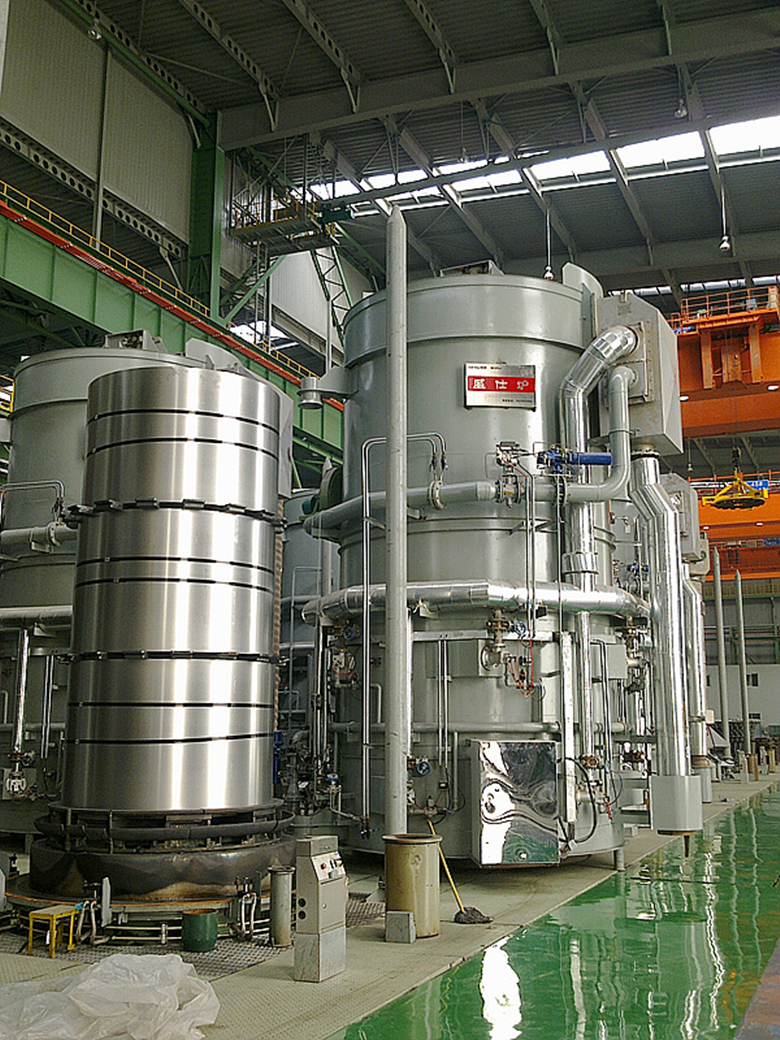
 is the preferred treatment, with box annealing of coils under a protective atmosphere being the preferred process ( producing what are known as CRCA or Cold Rolled Close Annealed coils). The protective atmosphere of for many installations is 96% nitrogen, 4% hydrogen and a dew point of \(-40^{\circ}C\)This is a non- explosive mixture affording a commercial quality surface brightness.The picture of a typical installation is shown in figure 14.

Modern installations use  pure hydrogen with a dew point of\( -70^{\circ}C\), as the heat transfer rate is increased from burners to coils, thereby markedly  increasing the productivity of the installation, in addition to providing a brighter surface on the coils.This is despite the more expensive protective atmosphere generators as well as the more expensive furnace equipment which can deal with the potentially explosive atmosphere.

11.2 Skin Passing
A cold reduction of 0.5 to 2.0% is given to the annealed coils to prevent the appearnce of "orange peeling" or " Luder Lines" in the forming process.


                               Figure 15

The diagram of a typical stress-strain curve as obtained from the tensile test of a specimen of low carbon cold rolled steel is shown at figure 15.

For the annealed sample the curve follows the trajectory of a straight line OA, a kinky line AB followed by a smooth curve BCD. The skin passed sample follows a straught line YB followed by the smooth curve BCD.The kinky line AB has been removed- and it is the kinky AB portion that is responsible for the Orange Peel and Luder Lines.Interstitial C and N atoms are responsible ; they pin the dislocations, which are unpinned on deformation; causing the discontinuous behavior of the yield point in the section AB.

Skin Passing is done on dedicated mills which are either 2-hi or 4-hi, the larger work roll  diameters of  2-hi mills being favored by some as they promote better flatness. Hardened forged steel work rolls with a Shore C hardness of around 100 are selected for these mills.In addition to the improvement of forming qualities, the process adds to the luster on the coil surface.

12.0 Finishing

Levelling,trimming,slitting and cutting to length are the standard processes applied before the material is packed for the customer.

Strip needs to be sufficiently flat for use.There are different standards which are applied,but all of them involve the cutting of a fixed length of  sample  (typically 2 meters)from the coil , placing it on a surface plate and measuring the maximum deviation in the sample from the datum level with appropriate measuring instruments.
If the deviation is  and the sample length is  then the function  or some expression involving it is used as a measure of flatness.


                                  Figure 16

Shown above is the basic principle of roller levelling in a strip. The actual levelling machine has seen recent developments designed to get the maximum possible flatness in annealed thin strip. The addition of tension in the line intensifies levelling action; this has created the new generation of tension levellers. An example is shown below:


                                  Figure 17

Slitters separate wide strip into narrower coils using multiple pairs of rotary cutters mounted on two arbors precisely set up with separators.An example of a typical installation is shown below.


                                    Figure 18

A trimmer uses two pairs of cutters only mounted on stub shafts, and the distance between each pair is freely adjustable between cuts. It is designed to remove any  damaged  edges; this is usually an intermediate step between processes  rather than a finishing one.

A cut-to-length line cuts sheets into accurate lengths for stacking in packets. Shears are of the guillotine type; the cutting sequence  integrated with the line speed to allow sheets to be cut accurately on the fly. The diagram of a typical installation is shown below:


                                    Figure 19

13 Quality and Use

The quality of cold rolled steel  sheet lies  mainly in its surface, uniformity( of gauge, flatness and physical properties) , and  formability . Surface is important because sheets are frequently used for panels and other enclosing surfaces of equipment and appliances which need to be visually appealing; uniformity because it is frequently the raw material for high speed production lines which need feed of a uniform quality, and formability wherever the application so demands.

Cold rolled sheet steel has demand for use in the  many segments of the manufacturing industry, particularly those which are consumer-driven.

A major use is in the manufacture of galvanized , galvalume and color coated steel, which has not been covered in this article.Galvanized corrugated sheet for roofing is a major raw material for  the informal housing sector.

Auto body sheet is the archetypal high end application, which imposes stringent quality parameters on all these, and other parameters. There are many other uses which call for less stringent quality.


Friday, January 20, 2017

MES for Hot Dip Galvanizing Lines-V


The Nature of Data in Enterprise Software.


In my first article of this series, I had talked about the reasons that interested me in this topic .

If I am going to design an enterprise-wide package for a steel producing company, I must understand and consider the nature of data: where it is generated, by whom it is entered, by whom it is used and for what purpose.

Accountants and production engineers in a Steel Plant typically look at data in different ways.An accountant needs consistent and verifiable data, either authenticated by the generating department, or generated by the Accounts department itself.The data is posted :either into Ledgers and Journals, or into a Computer Program by office staff trained and held accountable for accurate clerical work.Books of Account, and Management Information Reports for presentation to the Corporate Office or Statutory Authorities are prepared using this data.

Production shops, on the other hand, represent important "generating departments" in Steel Plants.The generating method is the time-honored production report.In a typical production shop (assuming that there is anything typical in a collection of production shops using such a wide variety of inputs and producing an equally wide variety of outputs) the report generation stage proceeds something like this:

Coal or iron ore stored in silos, a ladle of molten steel, an ingot, a bundle of rods bearing a specific batch number, a coil, a packet of sheets- all these can be inputs, and most of them can be outputs.It depends on the particular shop we are considering.
The input details are entered in the production report form.The unique identification no. has to be verified by the production department( for solid steel this number is usually written on the steel surface, else embossed in steel tags attached to the packet bundling wire, else pasted as paper labels on the top of the coil).Production practice may or may not call for weighing of the batch before taking it into production: in case the batch is not weighed, the output weight is taken from the production record of its previous process.
Output is usually weighed at the end of the process.On occasion weigh scales are not conveniently located, or may be under breakdown. In that case, typically "calculated" weights are used, with verification of output weights being (or not being) done at a different time and location.Sometimes the verification takes place weeks or months after production at the start of the next process.The delay is sometimes the result of a decision by Production Planning Department; sometimes the constraint is a purely physical one( material lying at the bottom of a heap).The environment is typically hot and dusty; the data is entered round the clock by production workers and supervisors primarily charged with monitoring and maintaining the production process.
In this environment the generated data is bound to be imprecise.The amount of imprecision in production data would depend entirely on the management structure, and also the data field involved.
Why should any attention be paid to imprecise data? Because they are ubiquitous, wide-ranging ,unbiased , consistently produced over long periods of time and cost virtually nothing to generate.Production engineers use statistical methods to analyze these reports to get valuable information which form the basis of quality improvement and cost-reduction initiatives.This information is valuable, available nowhere el else, and should be considered to be a data warehouse to be profitably mined at a future date.

Once we acknowledge the nature of production data, we can look at using a subset of this data, properly filter it to ensure consistency, and port it directly to the ERP. The filtration process will call for manual intervention; the more precise the shop-floor data, the less the filtration effort required.The architecture for the incorporation of production data into ERP software that emerges is a Data Warehouse application layer located below the ERP , to be used for Data Entry and Verification as well as Data Mining.

The only problem that remains is the impatience of Senior Management with the non-intuitive science of Statistics.If anyone tries to micro-manage a production process using discrete bits of data rather than taking a statistical view, he could end up by over-correcting the process, creating new problems rather than solving old ones.It is better to leave production management to professionals and hold them accountable for results.

I shall discuss my experience with the demo Data Mining program I installed in my next article.

Sunday, September 9, 2007

The MES Software Model

I have talked earlier about the importance of data in MES software.If I separate the software into "Data Consumer" or ERP,"Data Processor" or MES and the "Data Producer" which includes both the plant processor generated SCADA as well as the manually generated production reports, this allows us to move further towards data integration.
ERP providers typically build an enterprise model and constrain all other data inputs to fit( allowing for customisation).The SCADA providers typically cocentrate, as they should on running the production machinery in the first place, and offering use of historical data stored.No solution provider has as yet concentrated on the production report end.
It is in the interest of the users to come up with a specification or "contract" that will allow any ERP to combine with any SCADA and any provider of Production Report solutions.As a preliminary step I suggest the following:
For all Production Report functions:
1.The Data Consumer should accept data from only the Data Processor.
2.The Data Producer should provide data only to the Data Processor.
3.The Data Processor should obtain data only from Production Reports and SCADA(i.e. the Data Producer).
4.The MES data will be a superset of the ERP production data.
This will ensure that while MES reports will focus on an area totally different from the ERP, the reports will be consistent with each other because the underlying data are consiastent with one another.

Thursday, August 2, 2007

MES for Hot Dip Galvanizing Lines-V


A SAMPLE STOCK REPORT(SCREENSHOT)


Manufacturing Execution Software(MES) for Hot Dip Galvanizing Lines: an update.


The setup I described in my earlier blogs soldiers on. Here are some new developments:


  1. The configuration has been revised from an assembly of Local Server Units to one Central Server Unit surrounded by client computers forData Entry, Report Generation and admin.The revised setup is shown at Fig 1 at the start of this article.

  2. The Finishing section has been added incorporating finishing, packing, loading, shipping, warehousing, contractor payments , updated stock figures.

  3. Jasper Reports have been used for reports involving a lot of sub-groups and sub-totals.The output is slick and impressive.A sample is shown at the start of this blog.


About Me

My photo
-Steel plant technologist -Construction engineer. -Contracts Manager -Technical editor. -(Occasional )java programmer. -Physics teacher -Author -And now, doting grandfather.